The vehicles of the future are based on the convergence of a wide range of technologies. Electrification; sensors; connectivity; Cloud computing; Big Data; AI – they are all intertwined in functional safety and driver assistance features for autonomous vehicles.
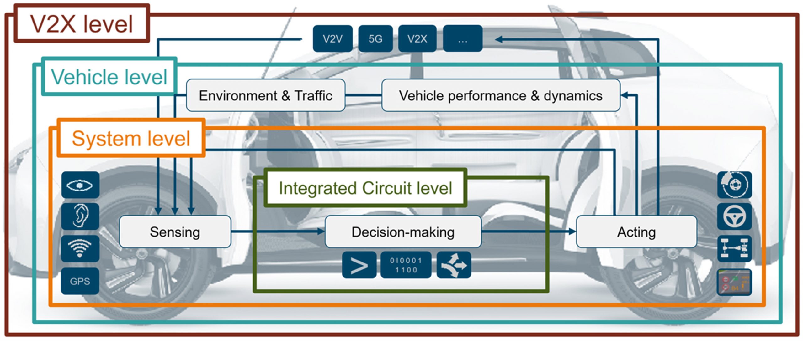
At the lowest levels, individual sensors and integrated circuits interact in the various subsystems of the vehicle. But it doesn’t stop there, the vehicle is part of a global environment that includes other vehicles, pedestrians, infrastructure and even the cloud. This makes checking automotive systems a huge task.
There are literally millions of scenarios to check out. And each of these scenarios has variations. For example, in one scenario, the car approaches a pedestrian in a crosswalk. But it could be at different times of the day, with different weather conditions and with different pedestrian clothing. This is all a verification project that realistically could never be done with physical means. All of these demands come together with the usual challenges of getting a competitively priced product to market as quickly as possible. The problem is perfectly suited to auditing tools that can make this process manageable. A combination of realistic scenario modeling, simulation and mechatronic verification aims to get a new vehicle on the road quickly and efficiently.
Figure 1: Vehicles are systems of systems, systems of systems.
For an autonomous vehicle to function, its systems must perform three tasks:
- Sense: the vehicle must be able to perceive its surroundings. In addition, many internal conditions must be detected to ensure proper operation.
- Decide: these sensor outputs must be evaluated to make decisions
- Operate: these decisions must control a part of the vehicle or an aspect of its operation. These three elements should be included in any comprehensive verification process.
And this presents a significant challenge, because there is no time to do physical prototyping using trial and error to find the problems. And it is impossible to thoroughly test safety and security in an actual physical vehicle. The only way to perform a thorough check is to virtualize the entire system – environment and vehicle. This means that we need tools to:
- Simulate real-world environmental conditions and the outputs of sensors that respond to them
- Check the circuits that perform the decision-making calculations, given the inputs from the sensors
- Make the calculated decisions and apply them to the virtualized versions of the mechanical systems that those decisions control
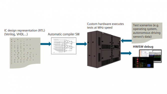
Figure 2: Veloce emulators take a design that was compiled for the emulator, run the design, and allow hardware and software debugging.
Modeling of the driving environment
In the first task, a tool broadly models the vehicle infrastructure such as roads (or portions of roads), bridges and intersections; physical objects such as trees, buildings and signs; other vehicles and pedestrians; and weather conditions. It also has a large library of modeled sensors, including cameras, radars, lidar, ultrasonic sensors, infrared sensors, V2X communications, and GPS. These elements work together to enable the modeling of realistic road conditions, with variations provided for time of day, weather, vehicle color or pedestrian clothing, pedestrian characteristics, and the many other ways these scenarios can be tested. Together, these virtual scenarios produce the signals generated by the various sensors of the vehicle when they react to the scenario. These signals can then be used to test the integrated circuits responsible for responding to the sensors.
Verification of integrated circuits
When it comes to checking circuits, simulation is a commonly used tool for checking circuit parts. But when it comes to verifying an entire chip, the simulation is way too slow. Much of the functionality will be implemented in software, which is virtually impossible to simulate – again, as it would take an extraordinary amount of time to do so. But there is a faster way to check silicon: hardware emulators. Unlike simulators, which use computer instructions to do their job, an emulator implements the verified circuit in logic chips that make up the heart of the emulator. In Siemens’ hardware emulator, Veloce, these logic chips were designed to allow them to implement any digital design within the size limits of the emulator. So while you’re not running the actual final silicon chip – which hasn’t been built yet – you’re still using hardware instead of software, and that can speed things up 1,000 to 10,000 times.
A key requirement of any verification approach is visibility. You have to be able to see deep inside circuits so that if something goes wrong you can understand exactly where and why it happened. You can’t do this with an actual physical circuit, because the overwhelming majority of signals never leave the chip – so they’re not visible. The simulators give good visibility, since everything is modeled in software, but, as we have seen, they are too slow. Critically, hardware emulators also provide the visibility needed to scan circuits the same way simulation allows, but with much faster execution speeds. The circuit you build inside an emulator acts as a digital twin of the real circuit. It allows you to develop a high quality circuit much faster.
This makes the verification much more efficient because you are testing the circuit before it is built. This means that there is no need to wait for the real silicon to do the verification. More importantly, you can find issues before committing to silicon, which greatly reduces the chances of an expensive and time-consuming mask re-tour and increases confidence when going into production. It is important to note that scenarios and results can be linked to requirements. This allows you to converge to a complete and correct design faster, since the verification plan and results remain tied to the requirements that motivated the design in the first place.
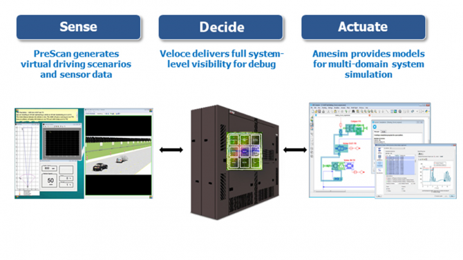
Figure 3: Together, Simcenter PreScan, Veloce and Simcenter Amesim provide end-to-end vehicle verification.
Verification of the answer to the calculations
Integrated circuits process sensor inputs and make decisions. It is important to verify that these decisions will have the desired effect. But the decisions affect mechanical systems that are not available in an emulator. A different tool is required for the hardware emulator output to continue in the system. Siemens has a tool that provides just such a capability, using Functional Mockup Units (FMUs) to simulate the effects of emulator outputs. It is still a virtualized environment – where one can test the activity of major mechanical components such as the engine, transmission, brakes and steering. So, for example, if a scenario shows a pedestrian unexpectedly jumping in front of the car, the camera and other signals from the sensors observing what is happening are passed to the emulator. The emulator decides, for example, to perform a steering avoidance maneuver, or to apply the brakes, or both. The logic signals indicating the decision can then be sent to the mechanical component simulation tool, where the flywheel will rotate by the requested amount, or the brakes will be applied by the requested amount, or both.
Verification of stimulus on response
Together, these tools provide the end-to-end verification that is so essential to ensuring that your vehicle will perform well in any scenario and regardless of the parts of the vehicle affected. And this is done in a completely virtual fashion, which means there is no delay in building prototypes. You just need to create templates – and many of them already exist in the tool libraries.

Jean-Maire Brunet, Senior Director of Product Management and Engineering for the Scalable Verification Solutions division at Siemens EDA
—————————————-
Jean-Marie Brunet is the Senior Director of Product Management and Engineering for the Scalable Verification Solutions division of Siemens EDA. He has spent more than 20 years in application engineering, marketing and management positions in the EDA industry, and has held IC design and design management positions at STMicroelectronics, Cadence and Micron, among others. Jean-Marie holds a Masters in Electrical Engineering from ISEN Electronic Engineering School in Lille, France. Jean-Marie Brunet can be contacted at [email protected]